● Voltage, current, power, resistance and temperature monitoring
● Testing passive audio systems or any transducer
● (woofer, micro-speaker, headphones)
● Monitors up to 32 DUTs simultaneously
● Reveals the destruction process in detail
● Stimulus shaping, cycling and stepping
● User-defined failure limits
● Monitors data of user-defined, external sensors (e.g., temperature & humidity)
● Control peripheral devices (e.g., heating chambers)
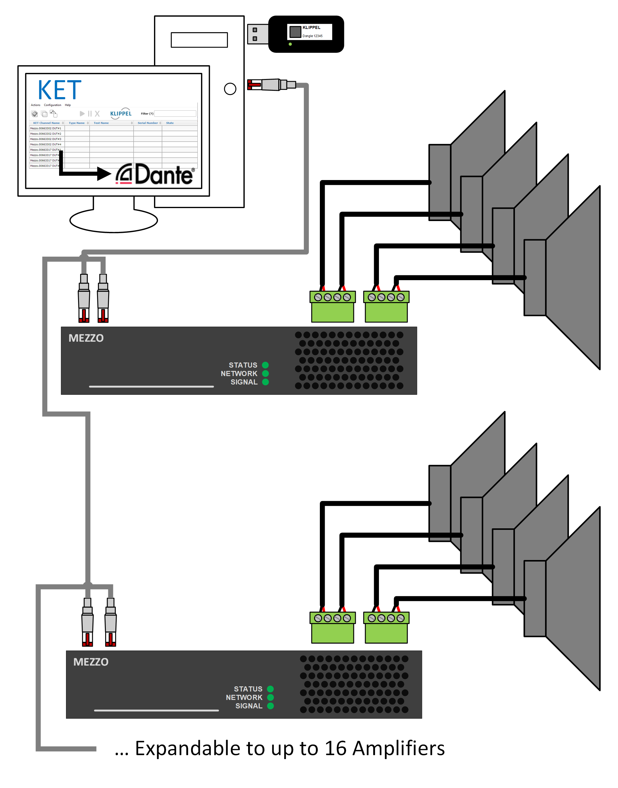
KLIPPEL Endurance Test (KET) solution provides a simple-to-use, cost-efficient soft- and hardware solution to run multi-channel long-term, power, and accelerated life tests for typical quality assurance (QA) applications such as validation checks or type approvals. Test signals can be defined flexibly using internal stimulus definition or customers wave files. Level stepping and cycling are available for any stimulus. Each DUT is monitored individually. Failures are automatically detected by checking against user-defined limits. Open and short circuits are detected by general limits; thus, a destroyed device is detected immediately. A “Death Report” reveals details of monitored states at the highest available rate for a limited time just before the failure was detected.
32 DUTs can be measured using one PC. Even a higher channel number up to max. 64 channels, depending on PC performance and Dante® Interfaces, is possible (see references). Each DUT test can be individually started, muted and terminated. Each DUT can have its own test signal and configuration. The current test status of all DUTs can be visualized in a dashboard. The dashboard can be easily accessed via any browser in the local network. Dante® technology is used for streaming data via a (wired) network connection.
KET follows our market-leading long-term testing solution Power Monitor 8 (PM8) with the Power Testing (PWT) module. Note that PM8 and PWT are deprecated. The following feature comparison compares our long-term test solutions and gives a general feature overview.
Continuous Testing
The simplest test is continuous playback of test stimuli for a defined duration. Monitoring power, temperature, voltage, and current reveals steady state performance for given environmental conditions. Thermal equilibrium may take hours to settle, especially for larger woofers. For mass production, regular statistical investigation of the fault rate may be required. KET eases this process considerably by using multi-channel tests and template-based setups applied to a given number of DUTs.-
 Voltage and Current
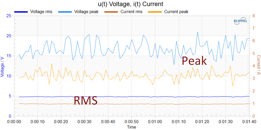
Power amplifiers used for KET are voltage driven, thus, the actual voltage at amplifier output can be monitored and compared with the specified level in setup. Current and voltage are provided as rms and as peak values. Potential clipping or power compression can be checked in the chart Device Compression / Limiter.
Voltage and Current
Power amplifiers used for KET are voltage driven, thus, the actual voltage at amplifier output can be monitored and compared with the specified level in setup. Current and voltage are provided as rms and as peak values. Potential clipping or power compression can be checked in the chart Device Compression / Limiter.
-
 Temperature, Input Power
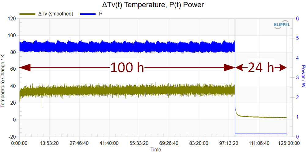
The voice coil temperature is closely related to the real input power supplied to the transducer. Note the dual Y axis in the chart. Both state variables plotted versus measurement time give important information for defining admissible maximal input power. For a continuous playback test the steady state temperature for the given level can be assessed.
Temperature, Input Power
The voice coil temperature is closely related to the real input power supplied to the transducer. Note the dual Y axis in the chart. Both state variables plotted versus measurement time give important information for defining admissible maximal input power. For a continuous playback test the steady state temperature for the given level can be assessed.
Accelerated Stress Test
Special profiles of excitation level and/or environmental conditions are used to accelerate the life cycle of a transducer. Fast changes in conditions stress the DUT and simulate a typical load scenario of product life in a much shorter time. One typical test (which is also used to determine the long-term maximum sound pressure level according to IEC 60268-21 cl. 18.4) is alternating high level with resting (cooling down). KET provides many options to alternate or step up/down the level for any kind of stimulus. Templates provide predefined setups according to international standards for easy setup and use.-
 Voltage Cycling
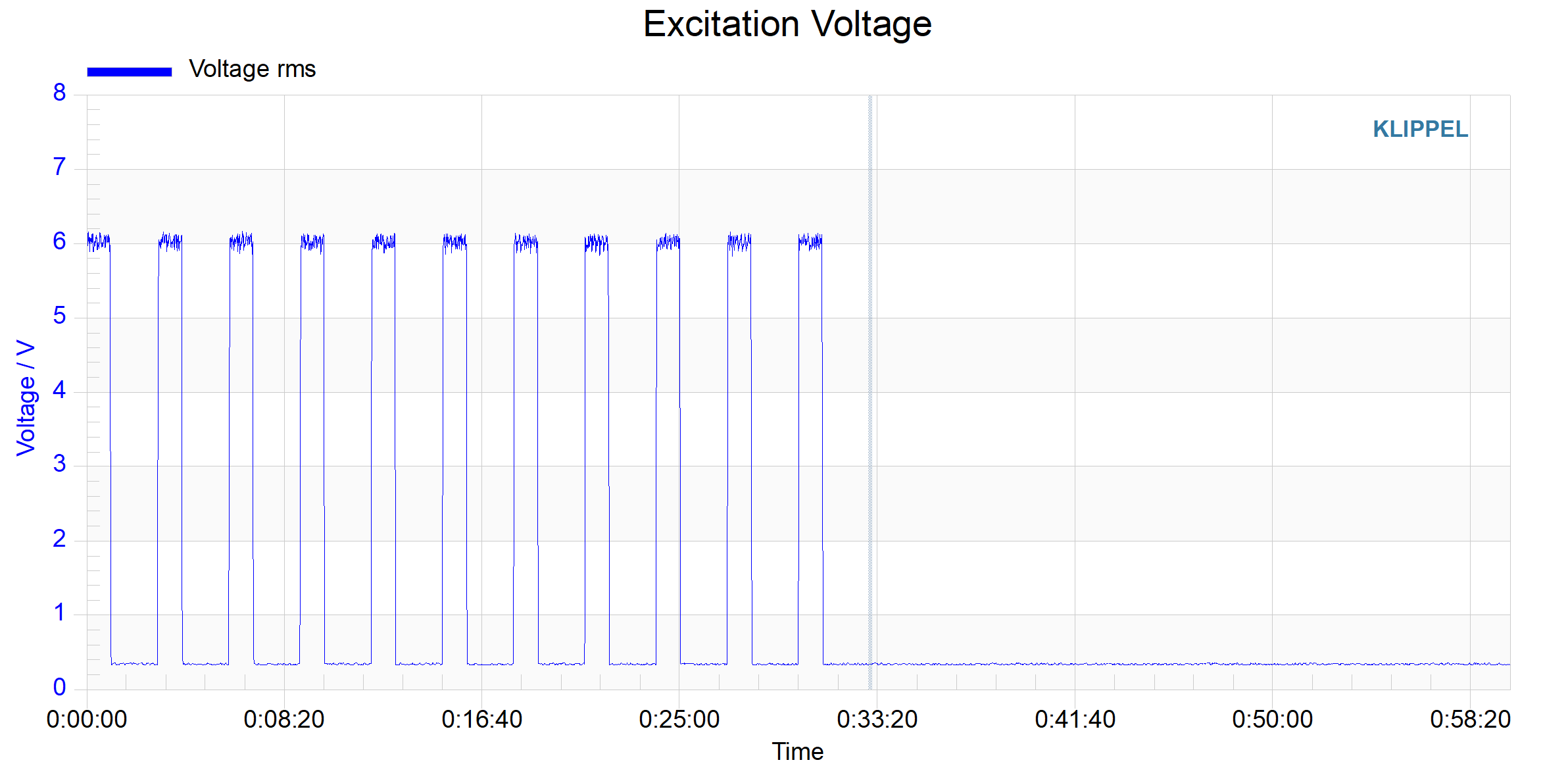
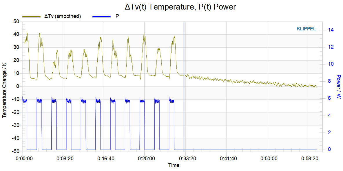
This test consists of 10 loops of a heating phase of 60 seconds at a maximum power level, followed by 120 seconds cooling phase with low or no input power. Arbitrary-level profiles are supported in KET.
Voltage Cycling
This test consists of 10 loops of a heating phase of 60 seconds at a maximum power level, followed by 120 seconds cooling phase with low or no input power. Arbitrary-level profiles are supported in KET.
-
 Temperature, Input Power
After the cooling phase, the voice coil temperature quickly heats up, increasing the input resistance of the DUT and therefore reducing the input power within the On-phase.
Temperature, Input Power
After the cooling phase, the voice coil temperature quickly heats up, increasing the input resistance of the DUT and therefore reducing the input power within the On-phase.
Destructive Testing
Most devices undergo thorough testing within their specified limits, but it's important to also test their maximum capabilities. Klippel Endurance Testing (KET) is a useful tool for determining the highest allowable power and coil temperature. The test automatically stops if the device is damaged or exceeds individual power, current, or temperature limits. The final 100 seconds of the test provide detailed information about the device's behavior during this crucial phase.-
 Temperature, Input Power
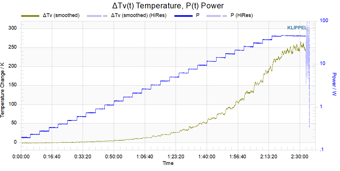
In this example, the test level is increased every 5 minutes by 1 dB steps up to a maximum test level of 25V / 45 W. Note the logarithmic y-axis for power. The device under test, a small automotive woofer that is specified with a 12V max rms level, withstands more than twice that specified level for about 5 minutes. The coil temperature at the breakdown was measured at about 250°C. Note, that the coil temperature is averaged over the coil, usually the outer parts of the coil are less cooled and may be considerably hotter than the inner parts.
Temperature, Input Power
In this example, the test level is increased every 5 minutes by 1 dB steps up to a maximum test level of 25V / 45 W. Note the logarithmic y-axis for power. The device under test, a small automotive woofer that is specified with a 12V max rms level, withstands more than twice that specified level for about 5 minutes. The coil temperature at the breakdown was measured at about 250°C. Note, that the coil temperature is averaged over the coil, usually the outer parts of the coil are less cooled and may be considerably hotter than the inner parts.
-
 Death Report
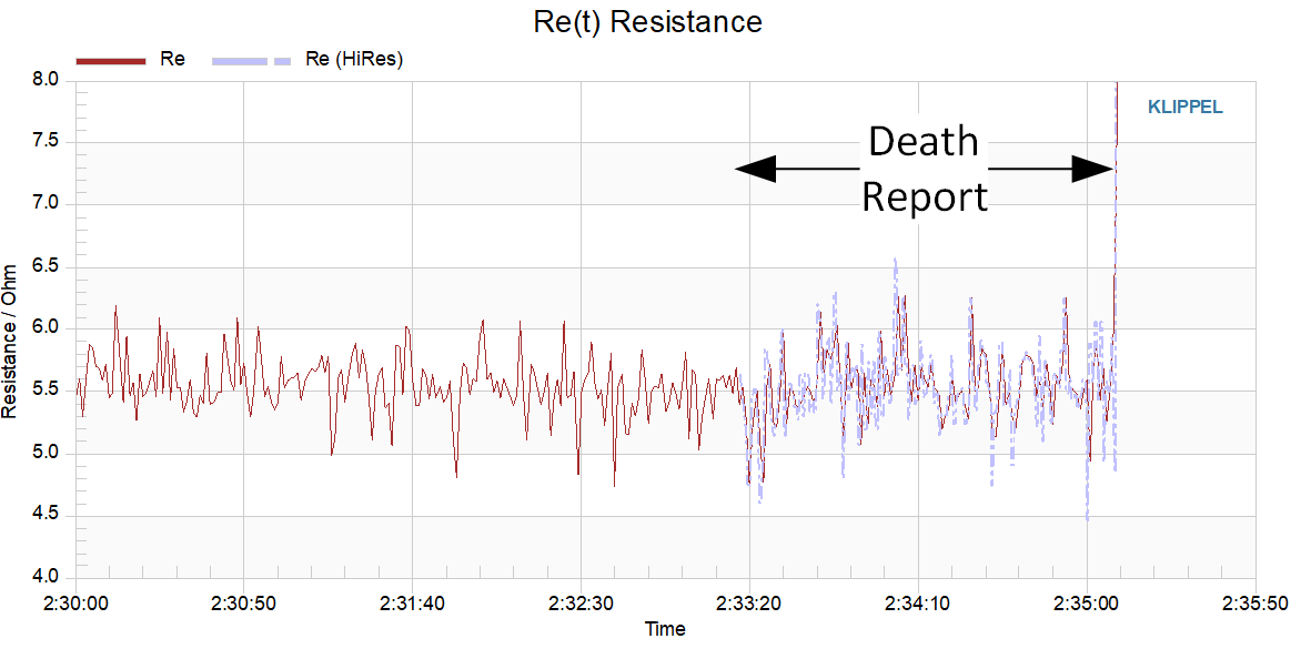
A death report provides high-resolution data just before a detected failure. A ring buffer of 100 seconds length stores results at the highest available rate, here about 200ms. This may reveal the root causes for a malfunction. In this example, the coil suddenly broke and the resistance jumped up quickly causing an open circuit failure.
Death Report
A death report provides high-resolution data just before a detected failure. A ring buffer of 100 seconds length stores results at the highest available rate, here about 200ms. This may reveal the root causes for a malfunction. In this example, the coil suddenly broke and the resistance jumped up quickly causing an open circuit failure.
Thermal Stress Test
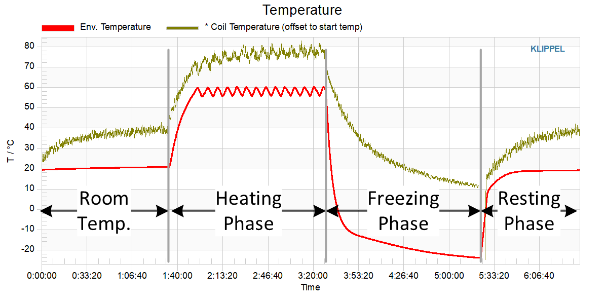
Thermal stress tests are part of environmental stress tests that can be performed or even combined by applying excessive heat, humidity, water, salt, or other aggressive chemicals to devices under test (DUT). Such tests prove the resistance of DUTs to tough environmental conditions that might appear in the final application. They are also part of accelerated live tests, which reveal aging and fatigue problems in a much shorter time than the actual product lifetime.A temperature sensor (red) measures the environmental temperature in a climate chamber while the voice coil temperature is plotted in brown. The test consists of 4 phases at room temperature, a heating phase, a freezing phase, and a resting phase, about 90 minutes each. Here the environmental heat and cold add additional thermal stress to the voice coil and the DUT, resulting in high coil temperature even at moderate excitation levels.
In this example, the external temperature sensor is automatically queried using an open API for any kind of sensor and included in result charts. Thus, other conditions using almost any digital sensor can be monitored and integrated into KET. Moreover, a software interface is available to control climate chambers or other instruments of torture for DUTs for automatic long-term tests with specific test profiles. As always after endurance testing, the compliance with expected behaviour shall be verified. Note that room temperature offset (20°C) was added to the measured coil temperature increase allowing comparison on an absolute scale.

 德国KLIPPEL产品中国区唯一指定代理商